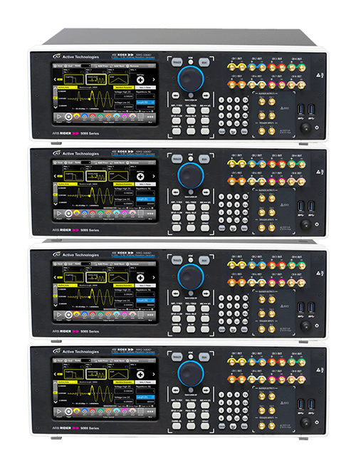
Wide base-band (1.5 GHz) RF signal generator
AWG-5000 Series Application Note – RF and Wireless Devices
Introduction
In the World of Radio Communications, signals are rapidly going to be all digital. This trend is mainly due to the better spectral efficiency that these have, compared to the analog ones. Signals central frequencies, spectral density and bands are increasing to satisfy the growing users demand; thus, devices are becoming more complex and critical in every operation they are requested to cope. For that reason RF Signal generator must be more and more poweful and capable to generare wide base-band signals.
Nevertheless, there are precise standards that must be met to market the product we are developing. This requires a full characterization of components, which, most of times, are quite different from each other and producing a specific test equipment for a single device to test is becoming too much expensive and unfeasible.
Here, the modern state of art ARB Rider AWG-5000 Series Arbitrary Waveform and Function Generators can overcome that problem, providing a flexibility that has never seen before, giving to engineers a powerful instrument to test a big variety of devices and appliances and speeding up test phases and reducing time-to-market.
RF Signal Generator
To transmit and receive information without using a cable, an electromagnetic field can propagate from an antenna to another and carry information on it.
However, the environment in which it pass through can be very noisy and significantly alter the transmitted waveform and, consequently, the data included in it.
Many problems affect the wireless communication, like signal attenuation, distortions, inter-channel interference and, especially in indoor situations or cities with high buildings density, multipath fading across the transmitted bandwidth.
To cope with these problems, many solutions have been introduced in modulation techniques, like spread spectrum over a bigger bandwidth and digital modulations with high symbol rates.
These waveforms are really complex and reproduce them with an instrument can be challenging, bringing most of times to require a device-specific test equipment, increasing costs and time-to-market.
In recent times a new instruments’ category is taking his space in this area.
These are called Arbitrary Function Generators (AFG) and Arbitrary Waveform Generators (AWG) that can act as evolved RF Signal Generators.
Their main ability is to be able to create a large amount of waveforms by directly synthesizing them (AFG) or by using a memory to store every sample value and then reproduce it at selectable output clock rates, even by looping, jumping and sequencing a portion of them (AWG).
The samples stored into the AWG devices can be created using an acquisition instrument like an oscilloscope or creating the waveform with a dedicated application.
Why Digital over Analog?
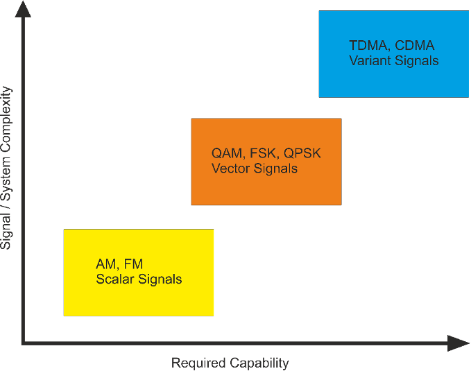
Analog modulations, like Amplitude, Frequency or Phase Modulation (AM, FM, PM) has been widely used in the past, since modulation and demodulation operations of these techniques are pretty simple and low cost (just think to AM which can be demodulated simply using a diode, a capacitor and a resistor).
All of them are made by simply modulating a carrier signal with an analog one which contains the information to transmit and vary, respectively, the amplitude, the frequency or the phase of the carrier (usually this last has a higher frequency than the modulating one).
However, since there is no encoding on transmitted signal, the only way to achieve a higher Signal-to-Noise ratio (SNR) is to increase the emitted power of transmitter, modulate over a bigger bandwidth and use high directionality and larger antennas. Every one of these has some problems: increasing the transmitted power is not always feasible, because electronic circuits have an increasing complexity compared to the power they have to manage, they become larger and need to be cooled.
Since channels count demand is increasing in order to allocate every application that needs a RF link, a strict regulation assign the maximum bandwidth that can be used.
On the last point, bigger antennas require massive structures to keep them in their position (they are usually also placed at high height from the ground) and directive ones don’t allow to broadcast a signal at the same power in every direction.
These reason and the increasing spread of digital devices, summed to the fact that, nowadays, processing digital circuitry cost decreased, brought to move in digital modulation techniques. This allow applications to gain a better SNR, more spectral efficiency and also some multiplexing modes not possible with analog modulation (like Code Division Multiple Access, or CDMA).
It is clear now that having an instrument capable of generate such a big family of waveforms, with one (or more) modulating signals and often also one or more carriers, adding them some noise as might be caused by environment noise, propagating interferences, demodulation and timing mismatches, brings to save a big amount of development funds and time.
A Tour into Digital Modulation
In order to transmit information “over the air”, splitting the common communication medium to allow different non-interfering data flows, we need to modulate a carrier (usually in radio or microwave band) with another signal (characterized by lower frequency with respect to the carrier) which contains the real content we are sending.
Both carrier and data signal can be either analog or digital and the choice depends by many factors. Most used rely on an analog carrier meanwhile, for above-mentioned reasons, nowadays it is common to have digital modulation. This consists in altering one carrier’s parameter (which can be amplitude, phase or frequency) using one or more symbols, represented by bits.
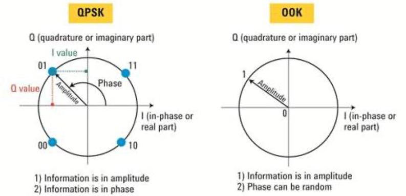
To understand what does it mean, let’s take a look to the simplest digital modulation: the On-Off Keying (OOK), a simple form of Amplitude Shift Keying with two levels (2-ASK); this consists in a two symbols (i.e. 0 or 1) digital amplitude modulation, so it is like switching on and off the carrier. This way, the presence of the carrier is coded into a “1” and the absence of it represents a “0”.Those two bits anyway could vary even one of the other two carrier’s parameter: by varying frequency we will obtain a two-levels frequency shift keying (2-FSK) or a 2-PSK (also called BPSK) if we are changing carrier’s phase on two levels.
It is not over though: the amount of symbols we use to encode the transmission affect both energy efficiency and spectral efficiency of the communication.
This represents a tradeoff, because as more as the first one grows, the more the second one decreases. Since the ability of capture and correctly read a signal with low signal-to-noise ratio is increasing, it is possible to lessen Eb/No ratio in favor of spectral efficiency.
Because of it, transmitted waveform’s complexity is becoming really higher and the bigger bps/Hz ratio can be reproduced only by a fast and flexible instrument.
Another modulation method that gained his space in modern communication systems is a special kind of amplitude modulation, also called Quadrature AM (QAM).
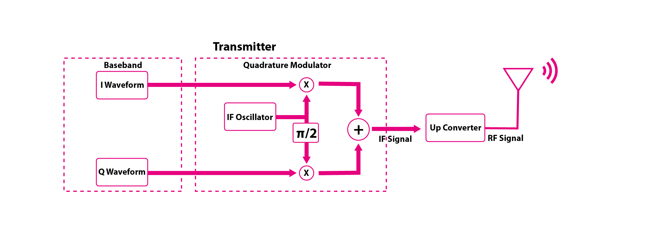
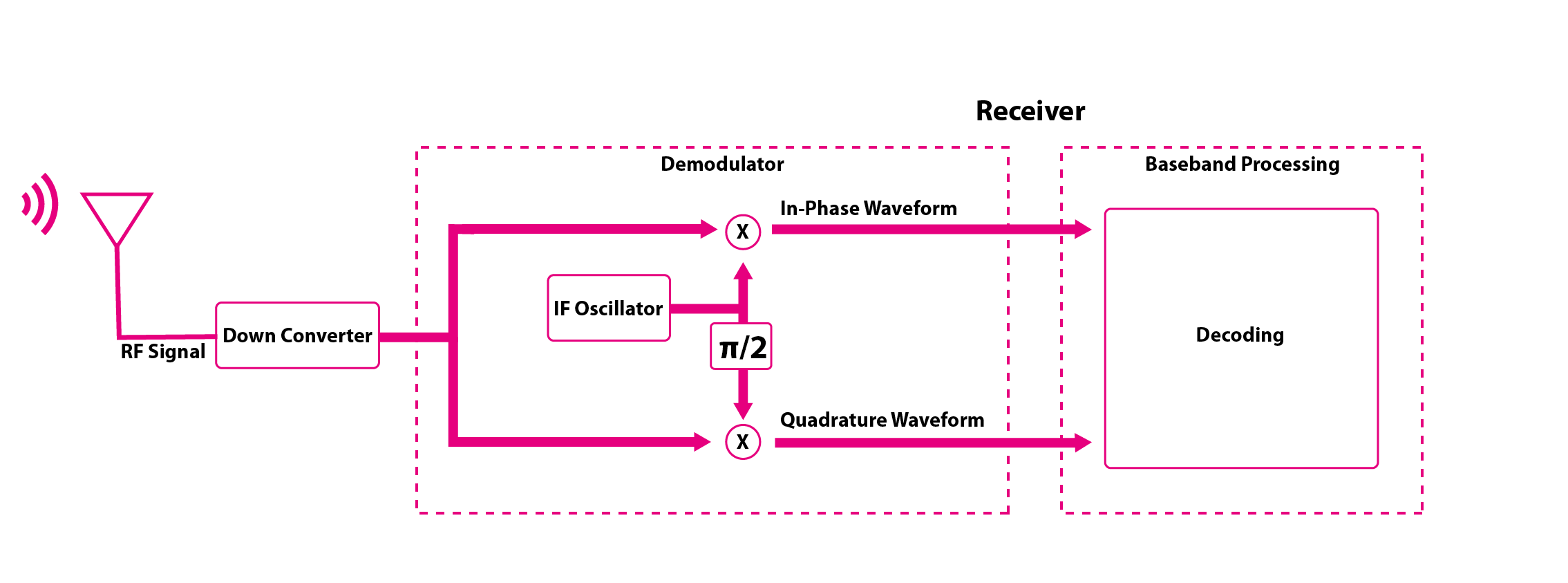
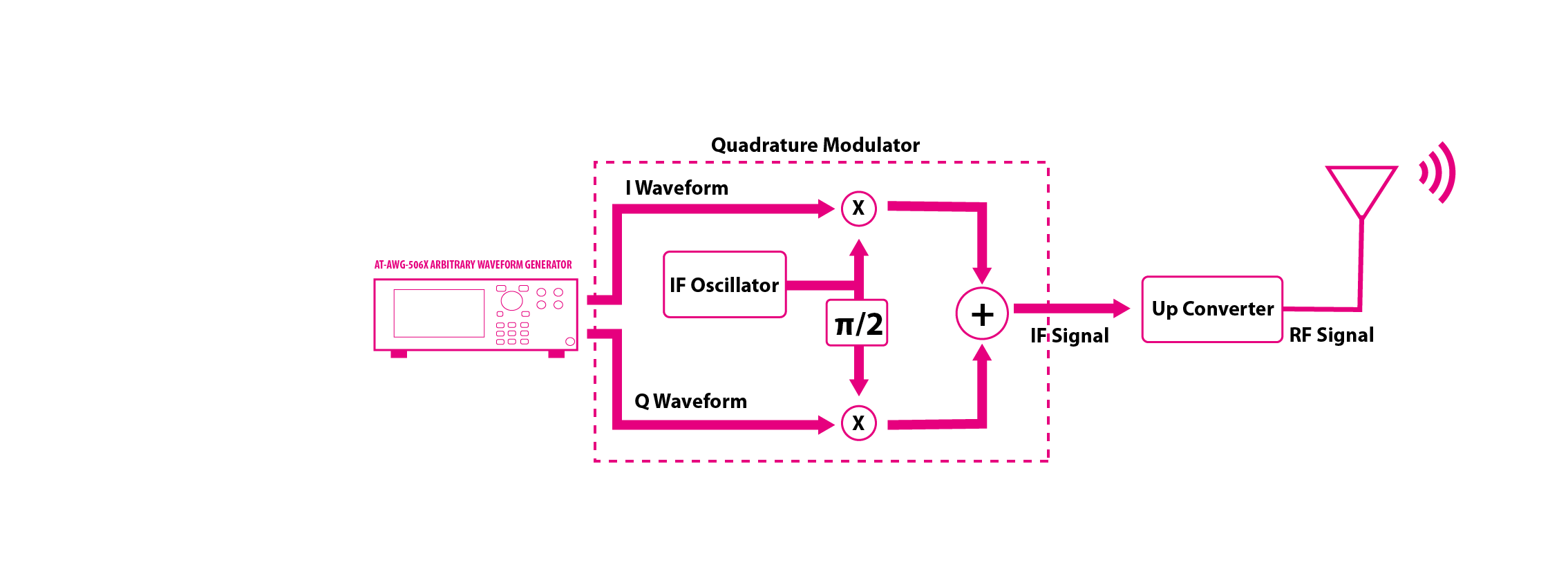
This one works by modulating, with the same information, two out-of-phase carriers instead of one and mix together those two channels. These are called I/Q channels, because one is in-phase and the other one is in quadrature with the first one (i.e. 90 degrees of delay), so the “I” channel carrier is a cosine and the “Q” channel carrier is a sine.
Summing them together, the I/Q relative amplitude can place a phasor vector on a discrete number of points onto a constellation, in which any point represents a transmitted symbol. By using a number of symbols in a power of two, we obtain that the number of bits to represent each symbol, therefore the amount of bits each symbol transport, is the base two logarithm of the total number of symbols. Not only amplitude but also frequency and phase can be put on a quadrature modulation in order to use coherent demodulation to better recover symbols and TX/RX synch.
A widely used is QPSK, which has a good spectral and power efficiency. In modern systems, is easy to see the use of high complex waveforms, which can be also a time-combination of the previous one, as it happens in Wireless LAN communication, in which the modulation is varied to a better use of spectrum if Signal-to-Noise ratio is enough in order to obtain big data-rate without occupying all the available bandwidth, or using a more power efficient technique, reducing bit-rate, if the used channel is noisy.
Other systems as in Bluetooth technology or in already mentioned WLAN, can jump from a carrier frequency to another to spread the spectrum and obtain a less power emission over a single band.
The law limits the effective radiated power of wireless devices, so spreading the same power over a wider bandwidth will decrease the average emitted power without dropping the S/N Ratio.
To better satisfy the increasing traffic requests, some of them also use Code Division Multiple Access (CDMA) in addition to Frequency and Time Multiplexing (respectively, FDMA and TDMA), which is a method that codes every symbol over a longer symbols’ sequence which can then be separated from the others at the receiver, even though they are travelling on the same carrier, at the same time but requires a higher bandwidth and faster modulators and demodulators (actually, a CDMA that uses codes made by 16 symbols, needs a bandwidth 16 times wider than without CDMA in order to keep the same effective bit-rate).
Another thing to consider is that we are still talking about digital signals: also bit’s shape has important consequences on the final global performance of communication systems.
Since the final signal’s spectrum is the Fourier transform of the bits’ shape, if we are using something near to a rectangle (as a bit is usually represented, not possible to exactly do a rectangle because it requires an infinite bandwidth), the spectrum will look like a sync, which spread power on a too wide bandwidth and will bring to interference with the near frequency channels.
A widely used filtering is called raised-cosine, which shape looks like a smoothed rectangle. The smoothness factor is represented by a parameter called alpha, which is directly proportional with the bandwidth of the final signal but also drive to overshoot and alteration of the original symbols’ constellation.
Seen how many complex operations are made to create a signal with the higher possible efficiency in terms of spectrum usage and power, should now be clear that to test all those devices requires to also build a full custom instrumentation.
The AWG-5000 Series Arbitrary Waveform Generator allows you to test any signal with a spectral component up to more than 2 GHz while keeping a Voltage resolution of 16 bits, which means that the vertical precision is higher than 1 over 65000 of the full voltage swing.
Advanced RF Signal Generator
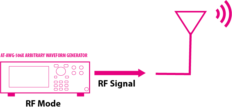
The AWG-5000 Series Arbitray Waveform Generator can work in Baseband mode with a Real Time sampling rate of 6.16 GS/s or in RF-Mode with an Interpolated sampling rate of 12.32 GS/s.
Using the RF-Mode, it is possibile to generate RF wireless signals and modulated pulses up to 6 GHz.
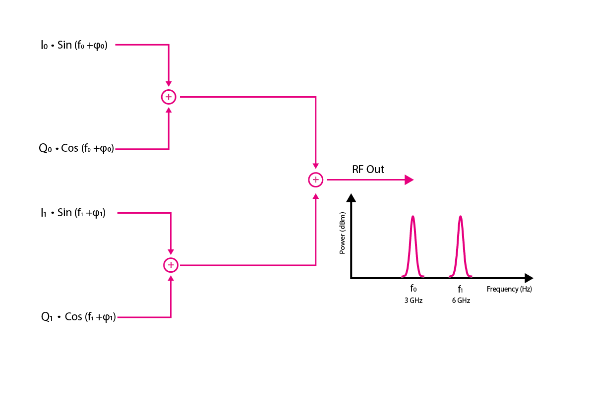
The internal modulator and up-converter allows you to create RF signals with one or two carries (Single and Double Carrier mode); using this mode it is possible to switch easily between two frequencies and add impairments in real-time like amplitude and skew between the different channels.
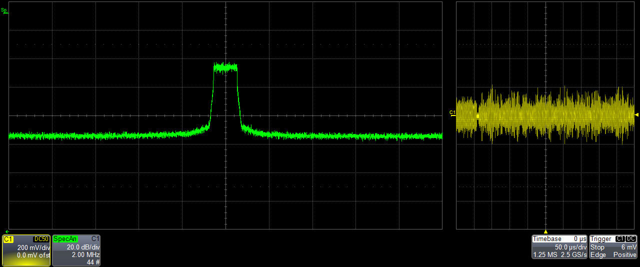
The AWG-5000 acts as an advanced RF Signal Generator with a wide base-band modulation capability with 1.5 GHz instantaneous bandwidth.
Up 2 independent carriers can be modulated with 2 independent I and Q data streaming (I0/Q0 and I1/Q1)
Common Implementations of Digital Modulation
Prompted by the digital revolution taking place in last years and helped by the decreasing cost of Digital Signal Processing (DSPs) and FPGAs hardware, engineers started to develop Software Defined Radio implementation, which use Digital Sampling and Filters (like FIR and IIR, Finite and Infinite Input Response filters) to build almost any kind of Wireless Device.
Nowadays these techniques are used in every application’s field, from consumers’ products to defense purposes.
Besides the already mentioned WLAN (formerly known as 802.11) and Bluetooth (used for Wireless PAN, which belongs to 802.15 IEEE standard), special attention must be given to Metropolitan Networks like Mobile Phones Communications, which rely on digital modulations since earlier versions like GSM (where the “G” stays for Gaussian, suggesting that the pulse shaping filter has Gaussian-like spectrum response) to modern implementations like HSDPA and LTE (also called 4G network) which uses CDMA and DSSS Quadrature Phase and Amplitude Modulations.
| Modulation | Application |
| MSK, GMSK | GSM, CDPD |
| BPSK | Deep space telemetry, cable modems |
| QPSK, π/4 DQPSK | Satellite, CDMA, NADC, TETRA, PHS, PDC, LMDS, DVB-S, cable (return path), cable modems, TFTS |
| OQPSK | CDMA, satellite |
| FSK, GFSK | DECT, paging, RAM mobile data, AMPS, CT2, ERMES, land mobile, public safety |
| 8, 16 VSB | North American digital TV (ATV), broadcast, cable |
| 8PSK | Satellite, aircraft, telemetry pilots for monitoring broadband video systems |
| 16 QAM | Microwave digital radio, modems, DVB-C |
| 32 QAM | Terrestrial microwave |
| 64 QAM | DVB-C, modems, broadband set top boxes, MMDS, DVB-T |
| 256 QAM | Modems, DVB-C (Europe), Digital Video (US), DVB-T2 |
In most countries also Television and Radio OTA transmissions are turning into digital modulations to take advantage of channel coding to be more reliable against noise and data compression to improve the usage of their dedicated spectrum sections and allocate all increasing users requesting to access it; noteworthy are DVB (both terrestrial and satellite television streams use digital modulations) and DAB (Digital Audio Broadcasting).
Another critical use of these techniques is for defense purposes, not just for communications, like TETRA, a standard mostly used for professional communications by police, firefighters and military forces, which also allows end-to-end encryption and multicast half-duplex transmissions and use a particular type of Differential Quadrature PSK called pi/4, because constellations are not orthogonal but with a 45° skew.
Also in Radio Detection and Ranging (RADAR) digital-based approaches are used to improve range and accuracy.
The following table gives an overview on Arb Rider AWG-5000 Series characteristics to better explain their capabilities and compare the features of our current instruments.
